A personal case study project in which I used the Blender addon bonsai to reconstruct my apartment as a BIM model, using data from 3D scanning and other measurement techniques to build a data-rich 3D model capable of generating an on-demand floorplan.
Background
In the spring of 2024, in preparation for a future sale, I decided to search for a floor plan for my apartment unit, but to my surprise, I could not find any plans or records. Before it became an apartment complex, the building was used as a convenience store in the 1950s. It was converted in 2014, which was before I owned the property. After speaking with neighbors, I learned that any existing plans were likely lost, as the company that renovated the complex declared bankruptcy in 2017, and some of the drawings went with them, including the one for my apartment.
With no existing drawings to rely on, I decided to create my own. I don't have a degree in architecture or engineering, but I am not completely unfamiliar with this type of work either. My day-to-day job involves the visualisation of offshore steel structures, so understanding construction drawings and detailed 3D models are not strange concepts to me.
Since I work a lot with 3D, I also find it easier to understand spaces through a 3D model than only through a 2D drawing. Because of this, I wanted to explore how I could create both a 3D model and a 2D floor plan without doing the work twice.
Research
My research for this project was guided by these aspects: how to represent the apartment in a 3D model that can also be used to generate a 2D floor plan automatically, or with minimal modification, when needed.
BIM
After doing some research, I discovered that this is a common problem faced by people working in architecture, engineering and construction (AEC) industry. The solution I found is something called Building Information modelling, or BIM.
But what does that actually mean?
Oliver Thomas from the YouTube channel ArchiTech Network gives a simple explanation of BIM:
"Bim is really just a 3D model and the moment it becomes a BIM model is when the geometry itself is not just a meaningless shape ,but it is packed full of data, and information inside the model"
— Oliver Thomas, ArchiTech Network WHAT IS BIM AND HOW IS IT USED IN PRACTICE?
In other words, BIM allows you to work with both threedimensionnaly as well as interact with underlying data and information simultaneously. On a BIM model, each element can contain information about what it represents, whether it is a wall, column, beam, floor, or another building component. It can also include data about materials, dimensions, quantities, and other properties.
I think many have to admit that BIM has become an unavoidable buzzword these days in the AEC industry. BIM is commonly referred to as both building information modelling (the process) and building information model (the digital artifact). In this project, I will use BIM primarily to refer to the modelling process, whereas for my 3D model I will call that a BIM model.
Bonsai
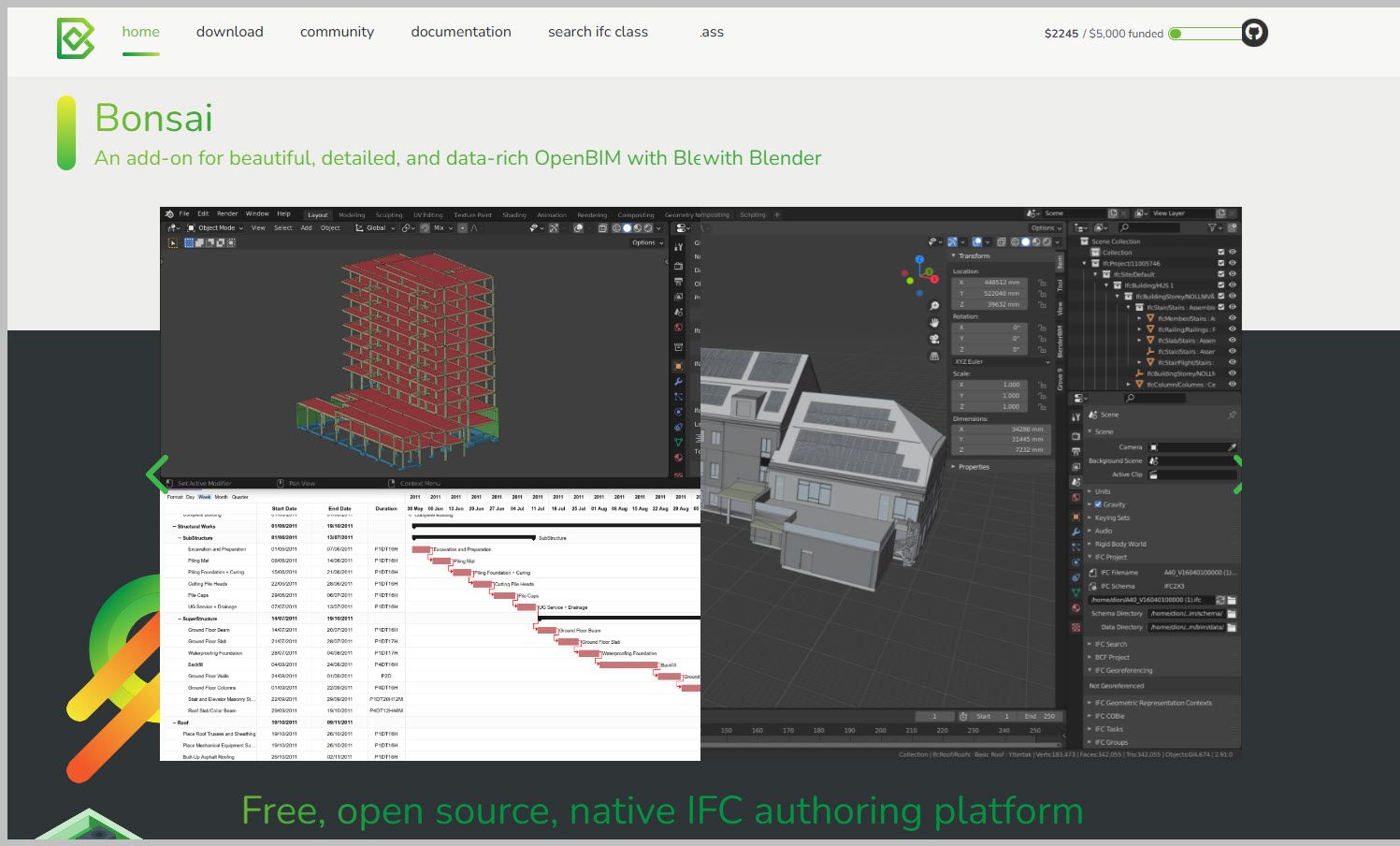
To build my own BIM model for this project, I will use a Blender addon called Bonsai, previously known as BlenderBIM.
In Bonsai all the interaction is through a dedicated modelling interface that interacts with IFC data model. IFC, short for Industry Foundation Classes, is an ISO standard that describes geometry, data, objects, processes, and relationships, in the built environment (i.e. BIM). Through this interface, I can create parametric elements such as walls, doors, and windows, and also generate 2D drawings from them automatically. This means the floor plan is not drafted separately as independent 2D linework, as in a conventional 2D CAD workflow.
Understanding the apartment layout
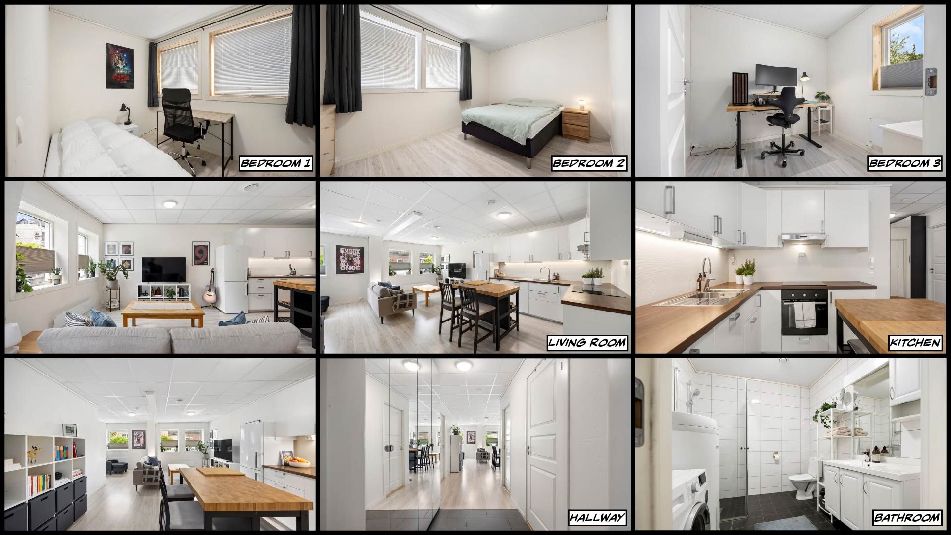
The apartment is a 3 bedroom, first floor apartment with a combined kitchen/living room space and one large bathroom, with a total of 74 m² usable area.
Rooms & Spaces
Here is a list of all available spaces:
- Hallway/entrance
- Bathroom
- Bedroom 1
- Bedroom 2
- Bedroom 3
- Living room/kitchen
When entering the unit, there are three bedrooms on the left-hand side. On the right-hand side, there is first the bathroom, followed by the pantry. Moving further into the apartment, you reach the combined kitchen and living room area, which is the largest space in the unit.
Measuring & 3D scanning
Before I could start modelling my apartment in Blender, I needed to collect enough real-world measurements to understand the apartment’s real size, proportions and layout.
I used 3D scanning together with manual measurements taken with a laser meter and measuring tape. For the scanning, I didn’t need anything too fancy, just something that could capture data accurately enough for this purpose. A colleague of mine recommended Scaniverse, a 3D scanning app for iPhones and iPads that uses LiDAR and photogrammetry. I don’t own any Apple products capable of running the app, but luckily I was able to borrow an iPad from work.
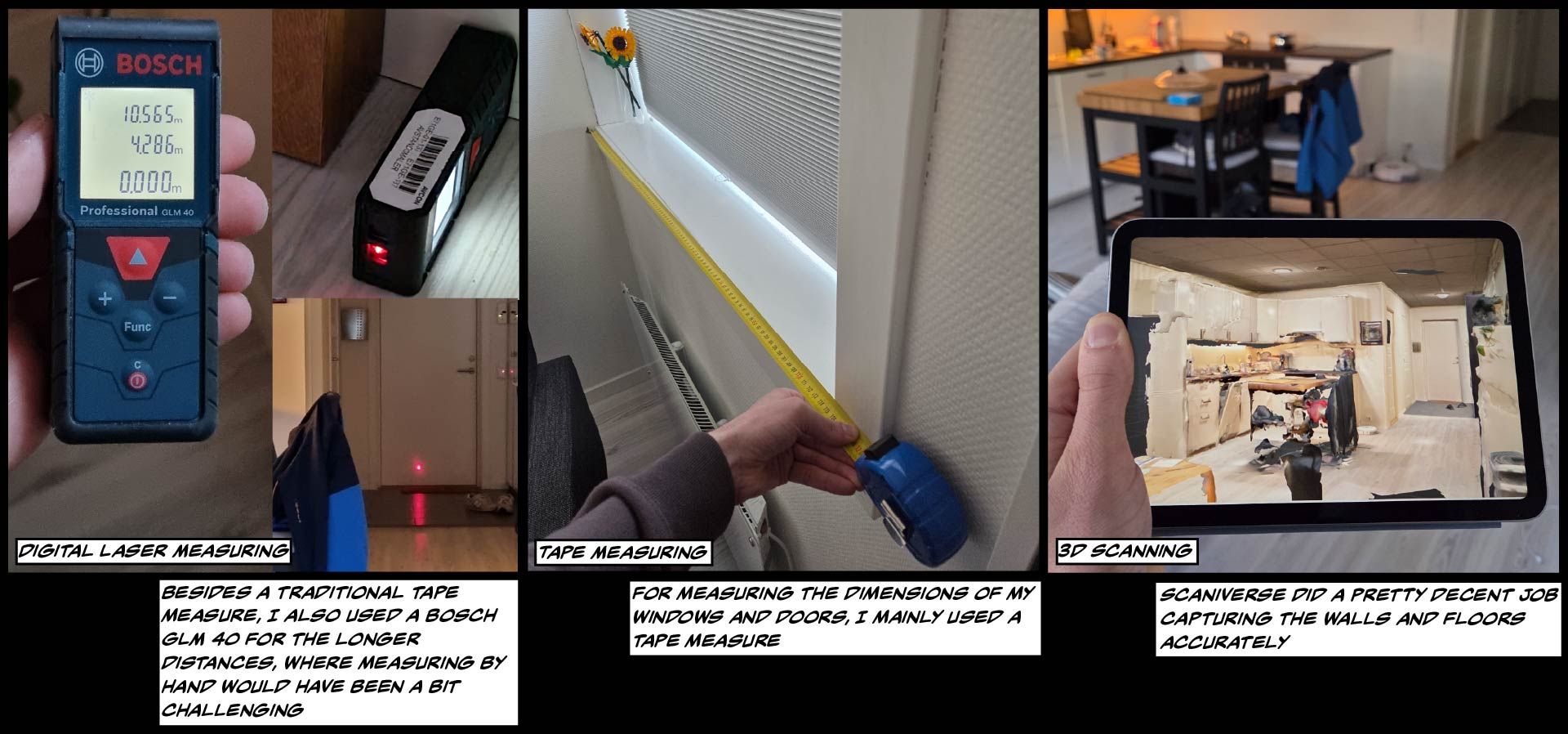
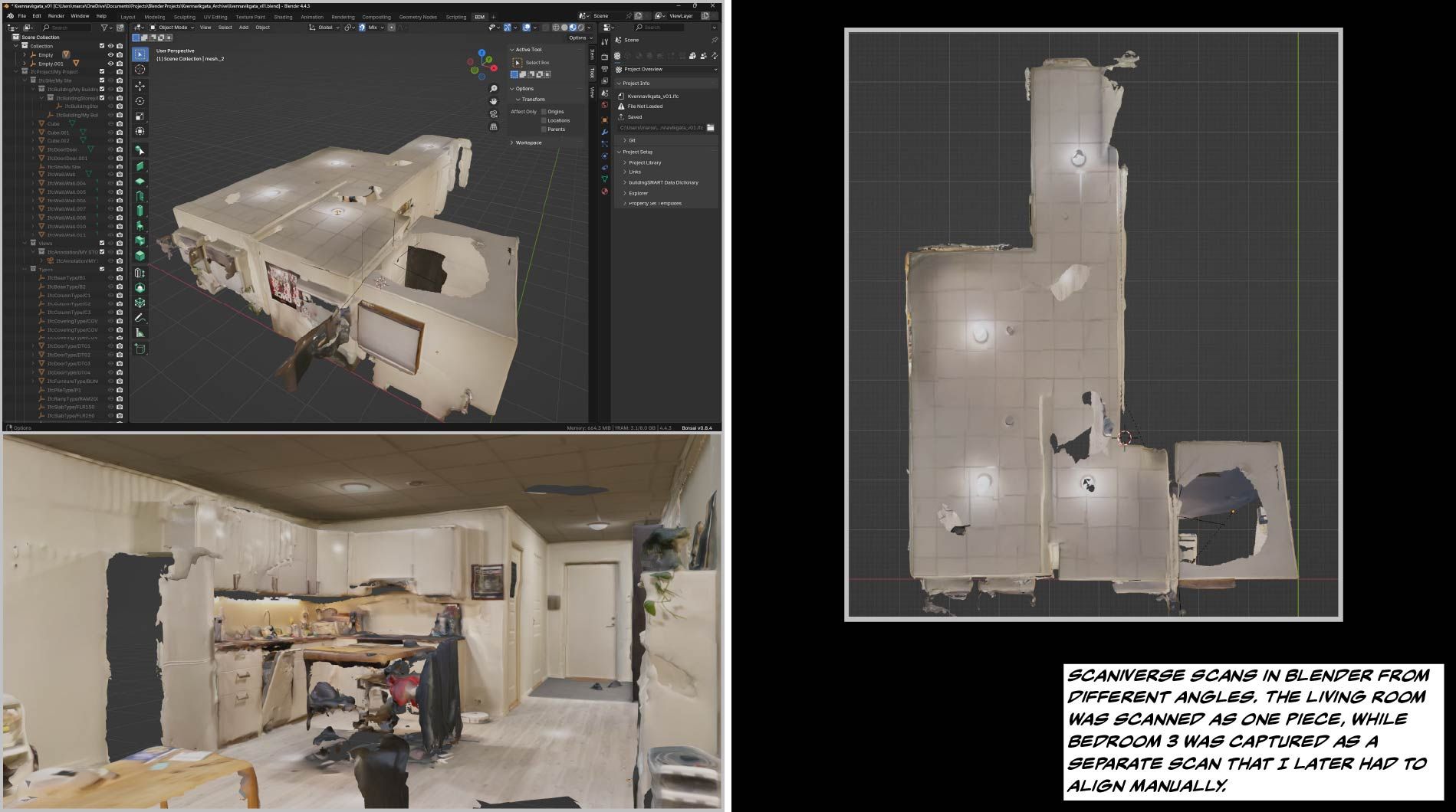
In total, I carried out two 3D scans that needed to be aligned with each other. The quality of the scans was sufficient for the purpose of the project. Given the layout of my apartment, I didn’t need to capture every room. Scanning the living room and the bedroom furthest from the entrance gave me enough reference to work from.
Building the apartment in Bonsai
The 3D scans were exported from Scaniverse as FBX files. In Blender, after resetting their origins, I needed to align the two scans. I used reference points from the door and from a shared wall that connected Bedroom 3 with the living room. The alignment was far from 100% precise, but more than good enough for the purpose of this project.
Saving files: .Ifc vs. .blend
In Bonsai, when you save a project, you use Save IFC Project, which stores the BIM model as an .ifc file rather than Blender’s native .blend file.
Regular Blender objects therefore do not automatically become part of the IFC model. For example, if I add a normal Blender mesh such as a cube or sphere, it will not be saved into the IFC file unless it is assigned or converted into an IFC element with a proper IFC class and representation.
Therefore, if I also want to keep any non-ifc-compatible objects in my scene, such as my 3D scans for this project, I need to save a separate .blend file as well.
Walls
In Bonsai, an IFC wall is a fully editable parametric and data-rich object. Just like columns, doors, windows, beams, roofs, and foundations, is controlled by settings specific to what that element represents. A wall can contain both structural and architectural information, including graphical and numerical data. Highlighting shows how object information is presented in Bonsai.
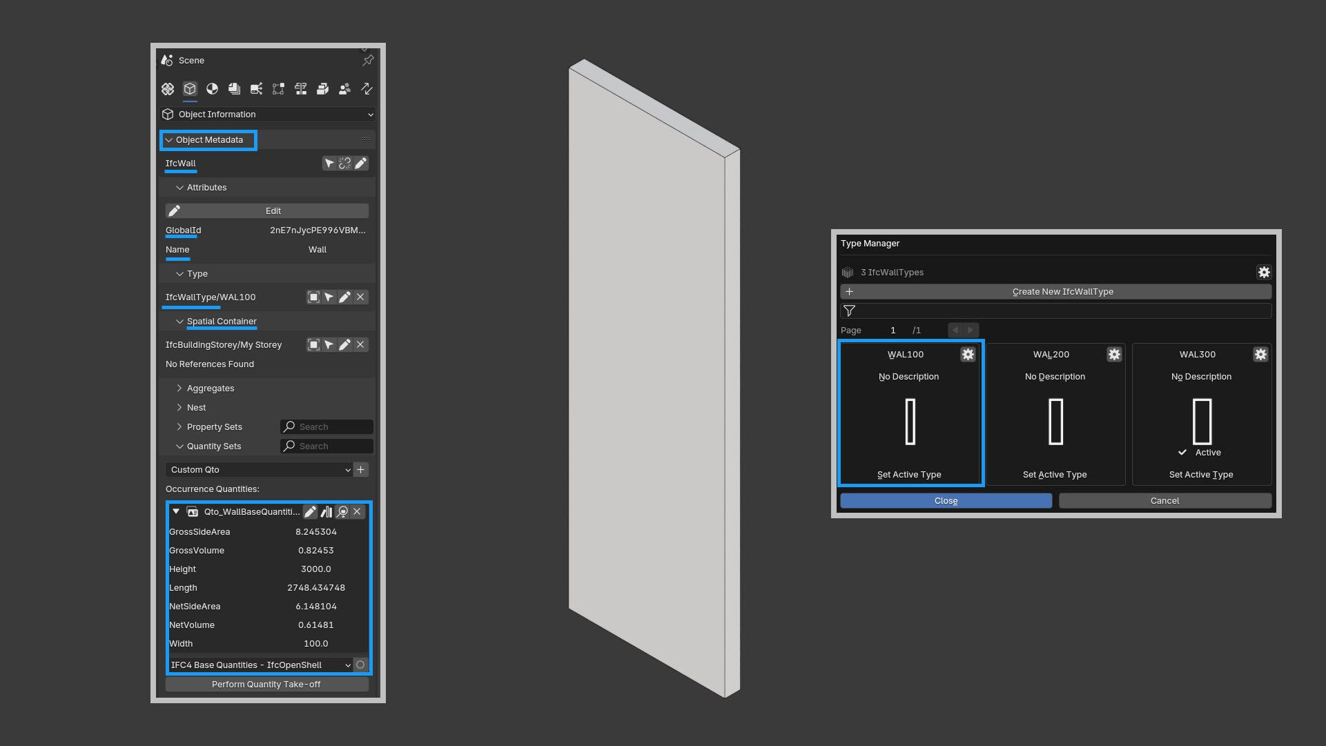
FIGURE 5 An example of an IFC wall
Wall types and libraries
Based on the measurements and scan data, I identified three different wall types: external masonry walls, internal plaster walls used as room dividers, and unit-separating walls that separate my apartment from the neighbouring units.
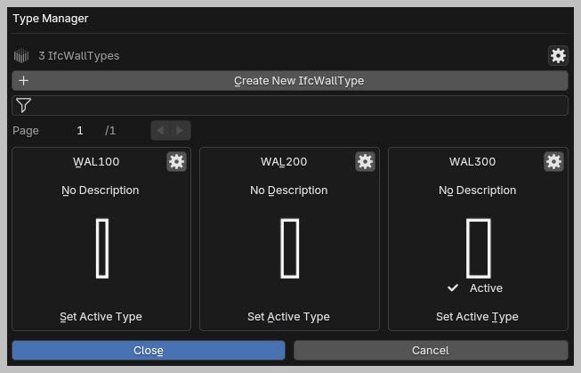
Using this data, I built a small library of IFC wall types with three different thicknesses: 300 mm, 200 mm, and 100 mm.
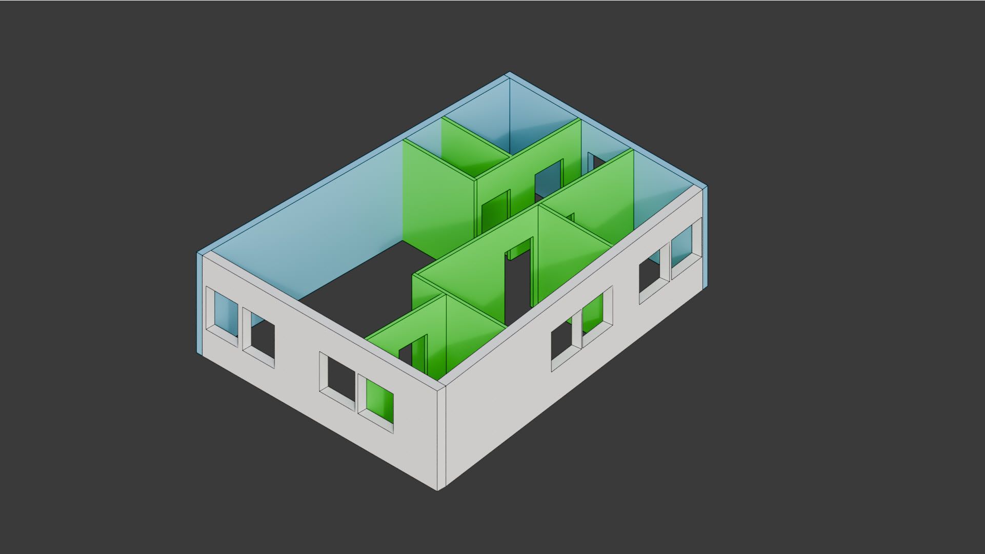
| Thickness | Wall Type | Colour |
|---|---|---|
| 300 mm | External / masonry wall | White |
| 200 mm | Unit-separating wall | Blue |
| 100 mm | Lightweight internal plaster wall | Green |
Openings
According to the buildingSMART definition, an IFC opening is a BIM object that represents a void, recess, chase, or hole within a physical building element, typically used to model spaces for doors, windows, penetrations, ventilation, access, or services.
Windows
I identified only two window types. The first measured 1300 × 1100 mm and had no handles or opening function. The second measured 1225 × 1195 mm and had a handle, allowing it to open. Both used a one-sided partition type. Partitioning type describes how a window is divided into panels or sections.
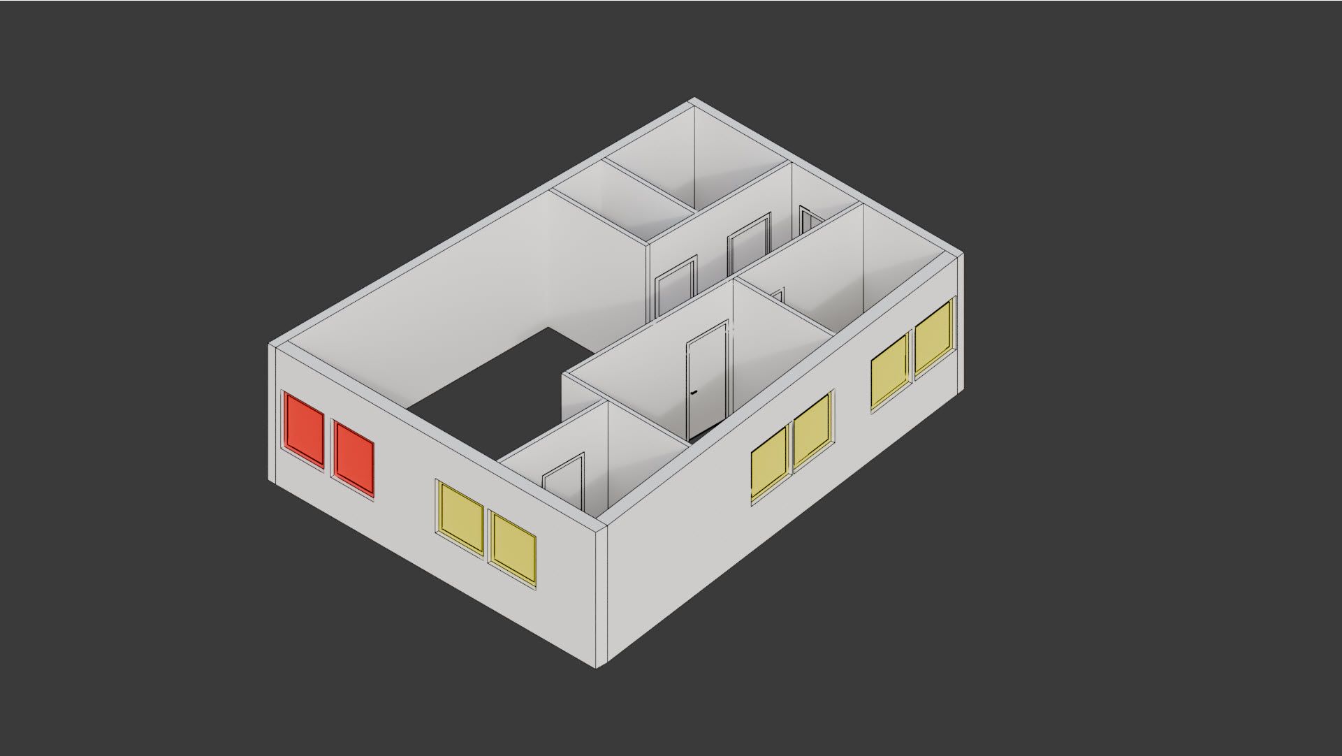
| Dimensions | Can be opened? | Colour |
|---|---|---|
| 1300 x 1100 mm | No | Red |
| 1225 x 1195 mm | Yes | Yellow |
Doors
For the doors, I also identified two main types. Most of them are lightweight internal plywood doors, measuring 2140 × 980 mm. There are five of these in total: four with a right-hand swing type and one with a left-hand swing type. The entrance door is much wider (2140 x 1000 mm) and heavier, than the inner doors,and it also has a left-hand swing operation.
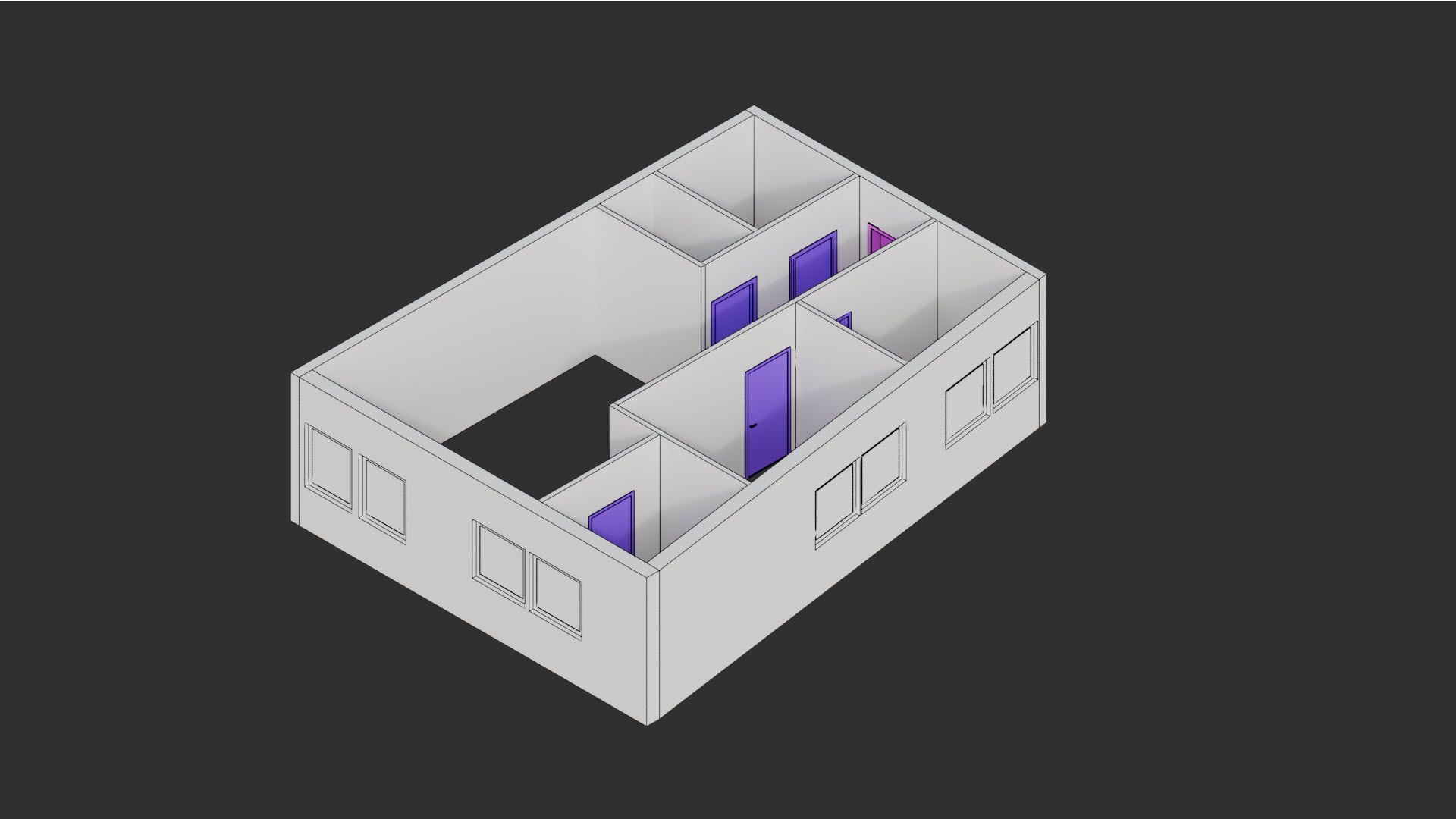
| Dimensions | Swing Operation Type | Colour |
|---|---|---|
| 2140 × 980 mm | Both left & right hand swing type | Purple |
| 2140 x 1000 mm | left-hand swing type | Pink |
Below is an illustration of the main entrance door swing. Door swing indicates the direction a door opens and which side it hinges from.
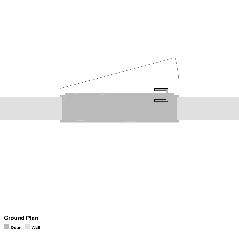 FIGURE 10 Top-view view example of a single door swing
Understanding drawing generation
In many traditional 2D CAD workflows, the drawing often comes first. An architectural plan or floor plan is created as 2D linework, from which any 3D representation can be generated later on.
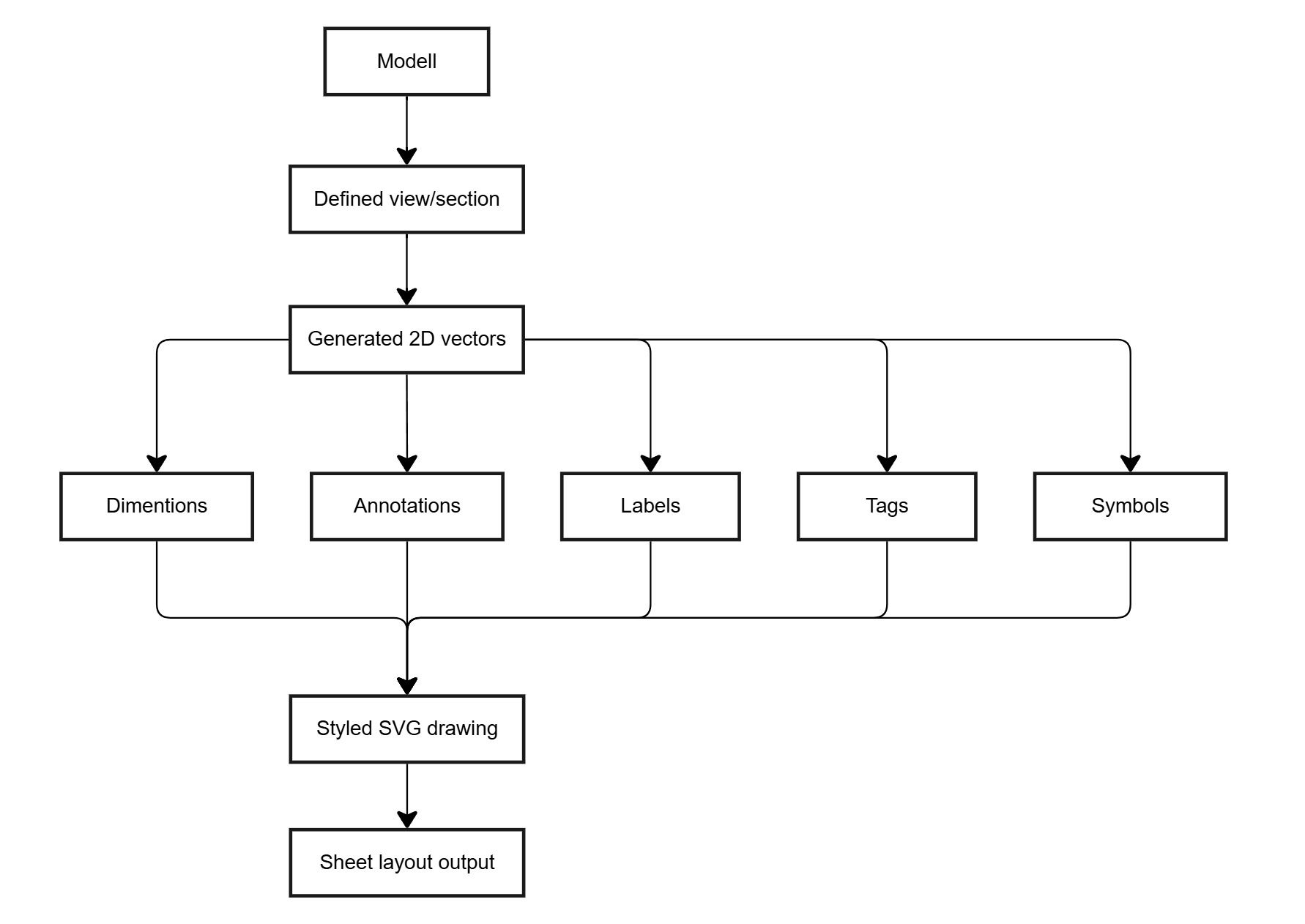
In Bonsai, the workflow is different. The drawings are generated directly from IFC BIM model. Bonsai does this by cutting through the 3D model at a set height and turning the visible elements into 2D linework. Dimensions, labels, tags, and symbols can then be added on top.
The drawing generator allows you to generate dimensions, annotations, labels, tags, and symbols. Standard items/classes such as walls, windows, door swing openings, will have annotations automatically generated.
Drawing generation in practice
Soo, how do you create your drawings in Bonsai exactly?
Once you have your IFC model, you create your camera view and add a new drawing. From there, you define the drawing scale and the size of the camera view. In my case, I used a 1:50 scale, with the camera width, height, and depth set to 15000 mm.
Now all that is left to do is click Create Drawing to generate the floor plan from your active camera view.
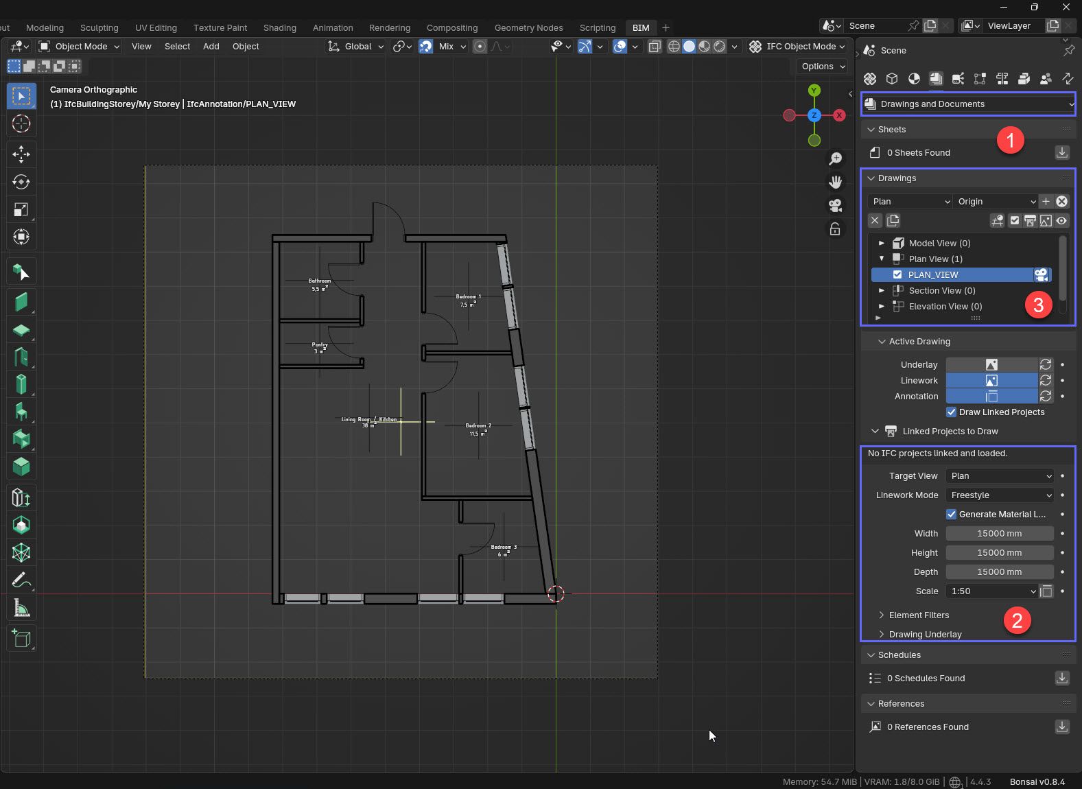
Here is a short walkthrough of where to find all of this:
- Navigate to the Drawings and Documents menu
- Adjust your camera settings
- Click Create Drawing to create your drawing
Floor plan
Down below you can see what my output was from the drawing generator. I only needed to manually add the room dimension labels.
Note that you need to have the Freestyle SVG Exporter addon installed. Otherwise, Bonsai will not let you output an SVG, and the button will stay greyed out. I may or may not have spent a few hours debugging this once, so I wanted to mention it in case you run into something similar.
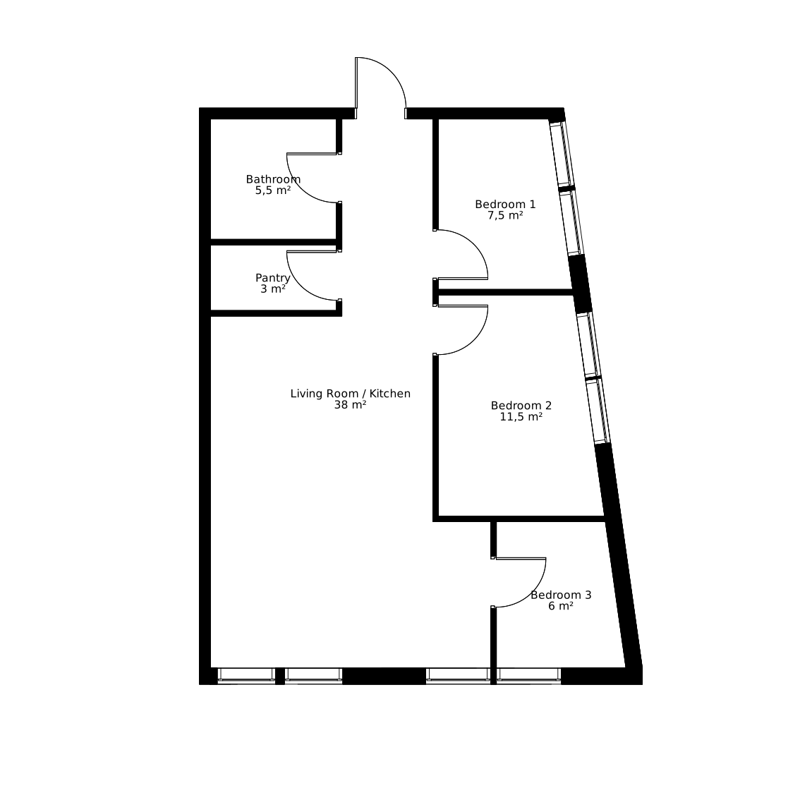
Turning the room dimension labels into smart text
As I mentioned, I added the room dimension labels manually, but you can turn these labels into “smart text” so they read and display information already available in your model.
You can turn a label into smart text by going to the Object Information tab. At the bottom, you will find a property called Product Assignments. Mine is already assigned to IfcSpace/Bedroom 1, but if yours is blank, click the pencil icon, then the eyedropper tool, and then click the object you want to read the information from. Make sure to click the check icon once you are done, so the changes are saved.
Next, select your label. In my case, this was IfcAnnotation/TEXT.005. Under the Object Information tab again, look for the property called Enable Editing Text, which is located under the Text property. Once you are in edit mode, go to the property called Literal: and type Name using two squiggly bracket each side. Make sure to click Edit Text so that your changes are saved.
Artistic Illustrations
This section goes outside the main topic of the post, but since I spent some time creating these illustrations for the project, I decided to include them here.
Site Illustration
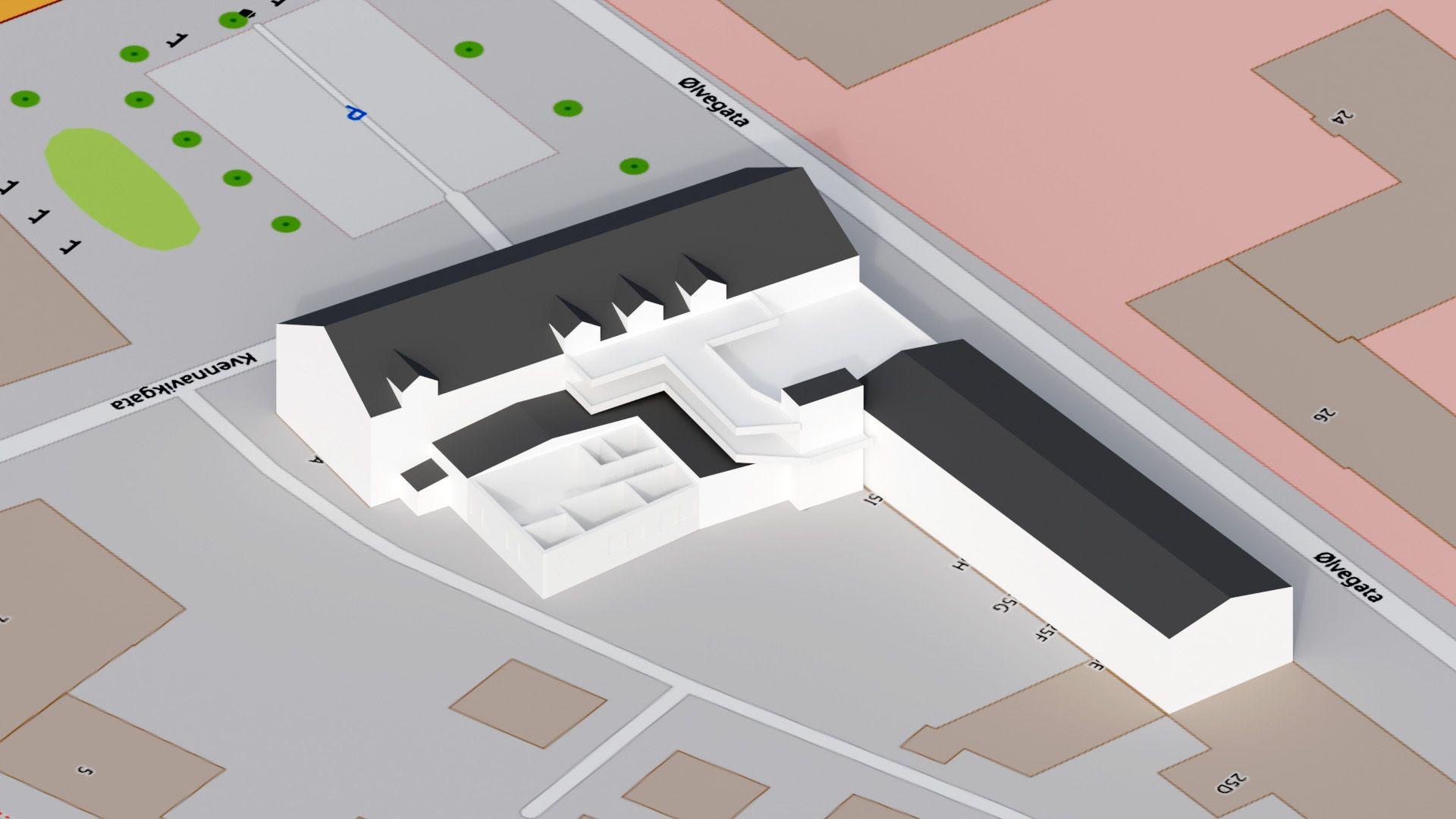
For this illustration, I recreated the building complex that my apartment is part of.
The background was created using a snippet of the northern part of the city of Steinkjer, using OpenStreetMap (OSM) data with the BlenderGIS addon. BlenderGIS can import geodata from OSM into Blender.
Once the map was complete, I integrated it with my apartment scene and began modelling the remainder of the building.
For the building complex, it was impossible to find any openly available data with information about the size of the overall building. Because of this, I had to rely on artistic interpretation and visual references from websites like Kommunekart 3D. Kommunekart offers detailed maps and aerial photos of Norway, making it possible to explore addresses, places, and properties.
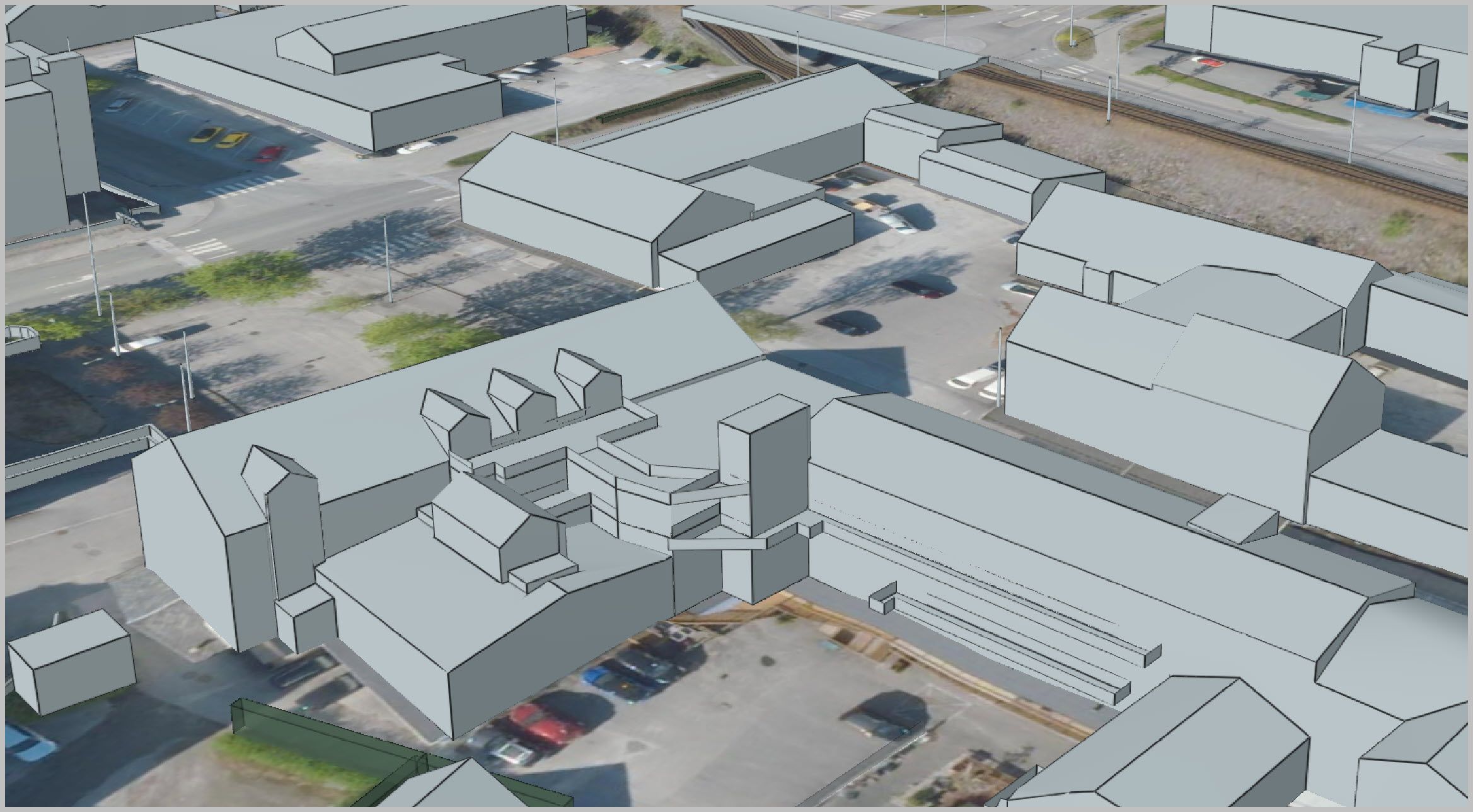
After the modelling was done, I set up a camera and added a material to give the illusion of a “roof.” The material uses the direction of each face normal, colouring the upward-facing faces to make them look as roof surfaces. Following that, I rendered the scene and used the image straight out of Blender, without doing any further post-production work on it.
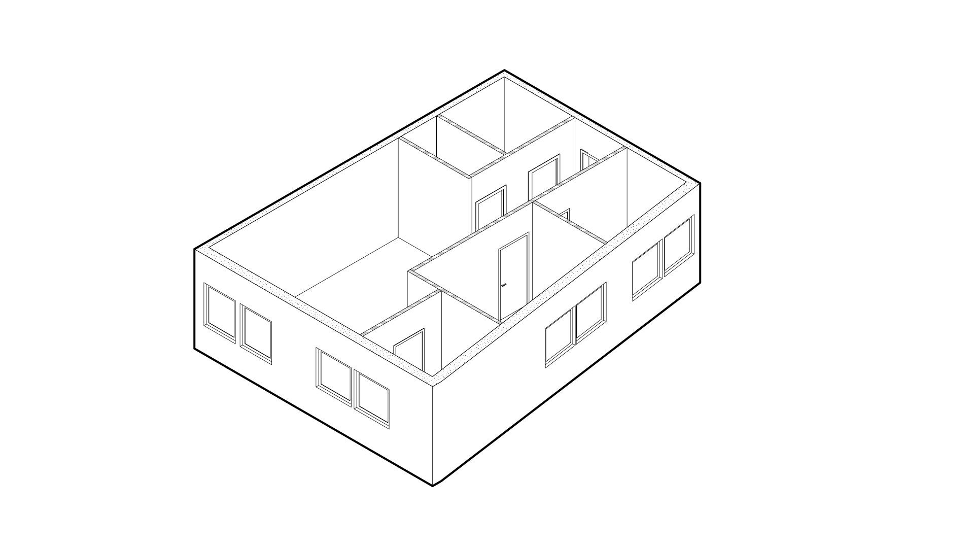
Freestyle Axonometric diagram illustraion
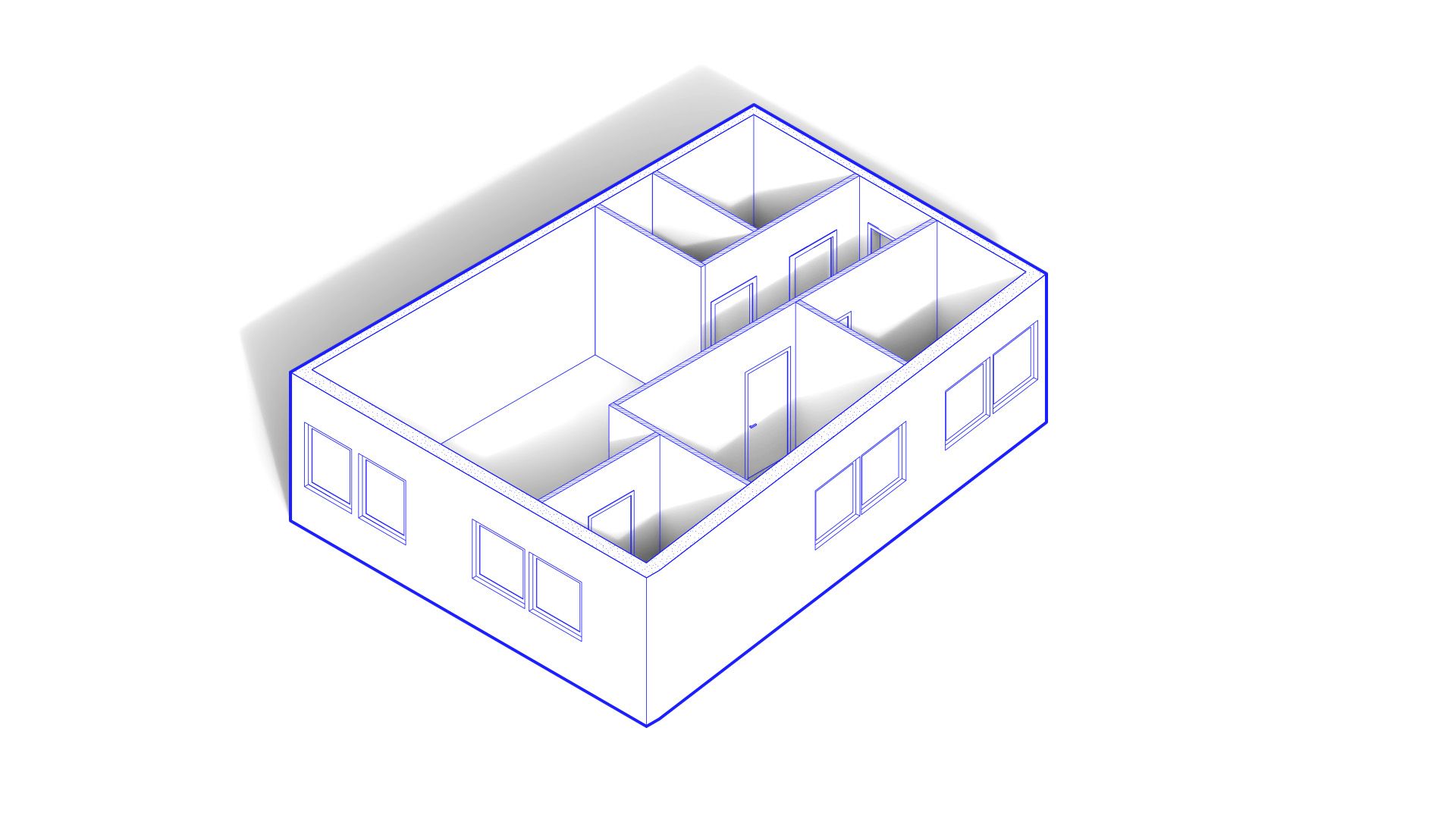
Another style I wanted to try was an axonometric diagram, a technique I see quite a few architects using. I wanted the illustration to have this “hand-drawn” feel, which I think works well with the visual direction of the project.
For the axonometric illustration, I chose an isometric view, which is a type of axonometric projection. To set this up in Blender, I added a camera to the scene, changed the perspective to orthographic, and set the camera's rotation to X = 54.7356°, Y = 0°, and Z = 45°.
Then, while my camera was still selected, I enabled both Freestyle rendering and the Freestyle SVG Exporter addon. Freestyle rendering creates lines around the visible objects in your render. By using Freestyle together with the Freestyle SVG Exporter addon, these lines can be exported as vector-based SVG lines.
I proceeded to render my image, and saved the output by adding the .svg extension to the filename.
With the saved SVG file, it was time to do some cleanup work in illustration. Passing the image through Illustrator is optional, but there is a good chance that the Freestyle output will produce lines that are not exactly how you want them. The lines can be very thick, sometimes causing the drawing to lose detail. A complex and detailed model can also create too much line detail, resulting in what I like to call “black blobs.”
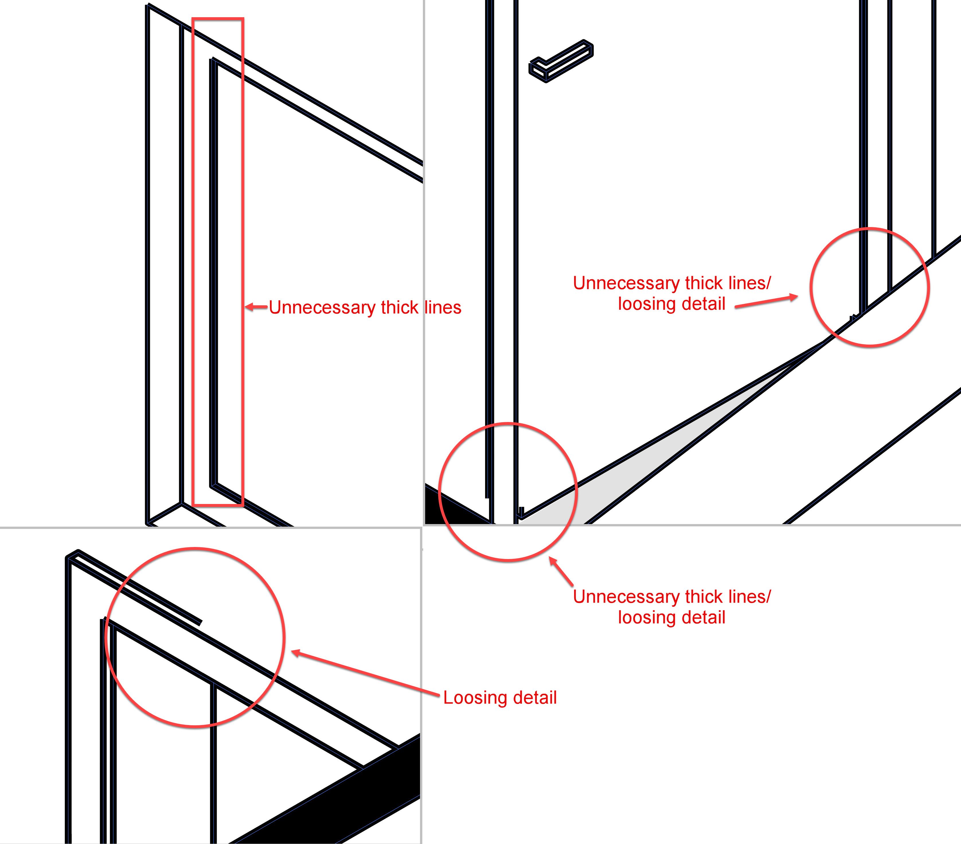
In Illustrator, I started by lowering the line weight to 0.75 px.
From here, I continued by organising the scene, grouping layers together, and creating selection sets. Then I added different patterns and hatches inside the walls. For the external walls, I used a concrete-like hatch. For the inner dividers, I used a lighter diagonal hatch to suggest something like wood framing. I also added a light grey shape for the floor and finished the illustration with a black outline to create the highlight effect.
With the cleanup finished, I moved over to Photoshop to do some final compositing. I rendered out a clay render from Blender and used it as an overlay on top of the Freestyle illustration to add shadows. Finally, I added a gradient layer to turn the black lines into a light blue colour, giving the image this “blueprint” style.
Architecture plan
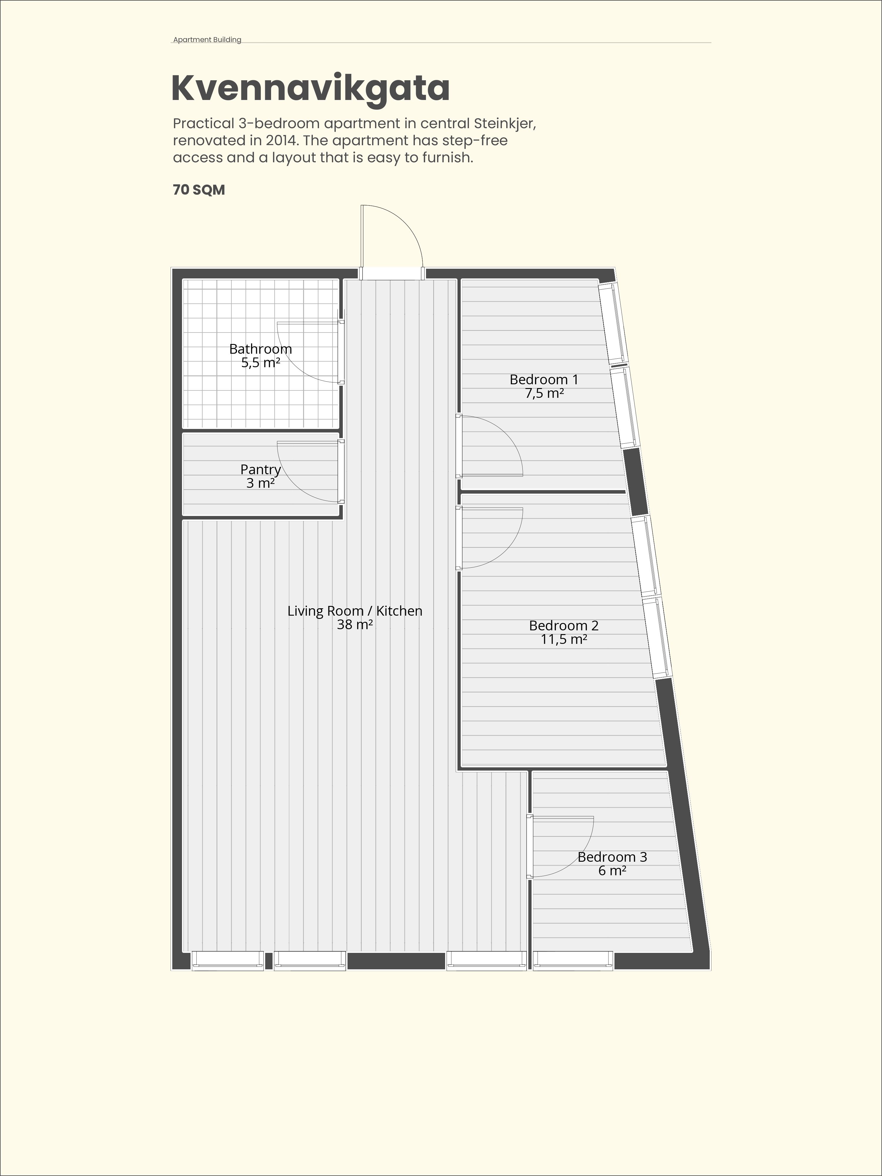
In addition to the original floor plan exported from Bonsai, I wanted to create a version that was not only functional, but also more pleasing to look at. The goal was to make something that felt more suitable for a presentation or portfolio, compared to the original unedited drawing.
I used the same SVG floor plan as a starting point. From there, I brought it into Illustrator and added text, a background, patterns, and colour to the flooring to create a clearer visual hierarchy. For the patterns, I created one line hatch for the flooring and one tile pattern for the bathroom.
After that, I made some finishing touches in Photoshop. One of these was adding an extra inner stroke to the walls using the Layer Style menu, which helped the wall outlines stand out more clearly.
Acknowledgement
I would like to thank my friend and former colleague Isak J. Bråthen for his ongoing efforts to teach me Blender-related skills for the past 5 years. For this project specifically, he provided assistance to the 3D scanning, showed me how to use the BlenderGIS addon, how to make a height-based colour mask using Blender's shader editor, how to render cryptomatte masks, which make it easier to isolate specific objects or materials during compositing, and some sick Miro tricks.